Leave Your Message
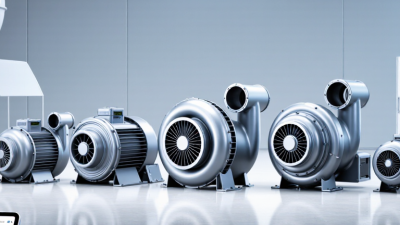
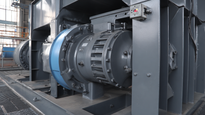
A Magnetic Suspension Centrifugal Blower uses magnetic bearings to support its rotating shaft without physical contact. This design removes much of the friction found in conventional bearing systems. A high-speed impeller then moves air through centrifugal force. Think of a compact wheel spinning inside a carefully shaped housing, producing steady airflow for demanding industrial equipment.
This technology is often applied in wastewater treatment, electronics manufacturing, HVAC systems, and process ventilation. Magnetic sensors continuously monitor shaft position. A control system makes rapid adjustments, helping maintain stable rotation. The result can include lower maintenance needs, reduced oil contamination risk, and improved operating efficiency. However, performance depends on correct sizing, installation, airflow conditions, and control quality. It is not automatically the best choice for every facility.
Real-world evaluation should include noise levels, pressure requirements, duty cycles, power consumption, and service support. Operators should also examine backup systems because electronic controls and power quality remain important. Small details matter. A poorly matched blower may waste energy despite advanced bearings. Maintenance teams need practical training, not just impressive specifications. This article explains how a Magnetic Suspension Centrifugal Blower works, where it delivers value, and which limitations deserve careful attention. Some claims require measurement under actual site conditions. That caution is necessary. Reliable engineering depends on evidence, operating experience, and transparent comparison rather than novelty alone.
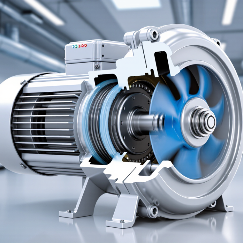
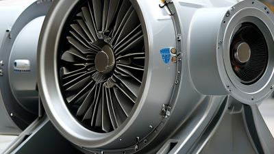
A magnetic suspension centrifugal blower is an air-moving machine that uses magnetic bearings to support its rotating shaft. The shaft floats without normal physical contact. This design removes much of the friction found in conventional bearing systems. An electric motor spins the impeller at high speed. The impeller then draws air inward and pushes it outward through centrifugal force.
The core concept is controlled levitation. Sensors continuously monitor shaft position, while an electronic controller makes tiny corrections. This keeps the rotor centered during operation. Because the bearing system does not require lubricating oil, the airflow path can remain cleaner. Noise and vibration may also be reduced when the blower is correctly selected and installed. However, “maintenance-free” is an easy claim to misuse. Filters, sensors, cooling parts, and control software still need inspection. Real performance depends on airflow demand, pressure, installation quality, and operating conditions.
Tips: Check the required airflow and static pressure before choosing a unit. Review filter loading regularly. A dirty filter can make an efficient blower work harder. Listen for unusual sounds. Small changes may reveal imbalance or control problems. Magnetic suspension is advanced, but it is not magic. Technicians should verify alarms, vibration readings, and emergency stopping functions during scheduled service. My practical view is cautious: lower mechanical wear is valuable, yet system design matters just as much.
| Data Dimension | Definition or Typical Data | Core Concept and Practical Significance |
|---|---|---|
| Basic Definition | A high-speed centrifugal blower that uses magnetic bearings to support and control the rotating shaft without physical contact. | The impeller accelerates air radially outward, while the magnetic suspension system keeps the rotor centered during operation. |
| Operating Principle | Electrical energy drives a high-speed motor; the motor rotates an impeller, which increases air velocity and pressure. | The blower converts electrical power into aerodynamic work through rotating motion and pressure generation. |
| Magnetic Bearing Function | Electromagnetic actuators generate controlled forces to levitate and stabilize the rotor. | Sensors continuously detect rotor position, and a control system adjusts the magnetic force to maintain shaft alignment. |
| Physical Contact During Normal Operation | No continuous mechanical contact between the shaft and the active magnetic bearings. | The contact-free support principle reduces bearing friction, lubrication requirements, and wear during normal operation. |
| Backup Protection | Auxiliary or touchdown bearings support the rotor during start-up, shut-down, power interruption, or control-system faults. | Backup bearings are not the primary load-supporting elements during stable, normal operation; they provide protection during abnormal conditions. |
| Airflow Direction | Air enters axially near the impeller eye and leaves radially or tangentially through the impeller and volute or diffuser. | This flow path distinguishes centrifugal blowers from axial fans, where air generally travels parallel to the shaft. |
| Pressure Generation | Pressure is produced by increasing the air's kinetic energy and then converting part of that velocity into static pressure. | The impeller supplies most of the energy, while the diffuser or volute helps recover pressure from high-velocity airflow. |
| Typical Speed Range | Often approximately 10,000 to 60,000 revolutions per minute, depending on impeller diameter, motor design, and duty point. | Magnetic suspension is well suited to high-speed rotation because it avoids many speed-related limitations of conventional oil-lubricated bearings. |
| Typical Airflow Range | Common industrial units may operate from several hundred to several thousand cubic metres per hour. | Actual airflow depends on impeller geometry, rotational speed, inlet conditions, system resistance, and the selected operating point. |
| Typical Pressure Range | Many applications operate from several kilopascals to tens of kilopascals of pressure rise. | The required pressure is determined by duct resistance, process equipment, filtration, water depth, or other downstream restrictions. |
| Motor Type | Usually a high-speed permanent-magnet synchronous motor integrated with or directly connected to the blower rotor. | Direct integration can eliminate couplings and gearboxes, reducing mechanical transmission losses and alignment requirements. |
| Speed Control | Electronic variable-speed control adjusts motor speed to match airflow and pressure demand. | Variable-speed operation can reduce throttling losses and allow the blower to respond to changing process requirements. |
| Lubrication Requirement | No continuous oil lubrication is required for the active magnetic bearings. | This can help prevent oil contamination in clean-air applications and reduces routine lubricant management. |
| Mechanical Wear | Very low during normal levitated operation because the main rotor support is non-contact. | Wear can still occur in backup bearings or other mechanical components during transient events and maintenance activities. |
| Noise and Vibration | Potentially low mechanical vibration because rotor position is actively controlled and direct-drive components may be used. | Total sound level still depends on aerodynamic noise, rotational speed, enclosure design, inlet and outlet silencers, and installation conditions. |
| Efficiency Consideration | System efficiency varies with airflow, pressure, speed, motor efficiency, controller losses, and operating point. | Magnetic bearings can reduce mechanical losses, but the complete blower system should be evaluated rather than bearings alone. |
| Control System | Typically includes rotor-position sensors, magnetic-bearing amplifiers, a digital controller, motor controls, and protective logic. | The control system coordinates levitation, speed regulation, overload protection, fault detection, and controlled shutdown. |
| Common Applications | Wastewater aeration, pneumatic conveying, combustion air, industrial process air, cooling, and clean-air systems. | The technology is particularly useful where oil-free air, high reliability, variable flow, or reduced maintenance is important. |
| Main Advantages | Oil-free operation, reduced bearing wear, high-speed capability, compact direct-drive construction, and controllable airflow. | These advantages may improve operational cleanliness and maintenance intervals when the unit is correctly selected and installed. |
| Important Limitations | Higher control-system complexity, dependence on sensors and electronics, backup-bearing requirements, and sensitivity to installation conditions. | A reliable power supply, suitable protection, correct commissioning, and planned maintenance are essential for dependable operation. |
| Selection Parameters | Required airflow, pressure rise, inlet temperature, altitude, gas composition, power supply, noise limits, and duty-cycle requirements. | The blower should be selected from its performance map so that the operating point remains within the recommended stable range. |