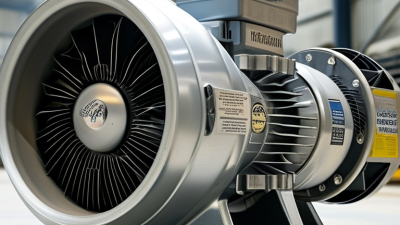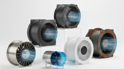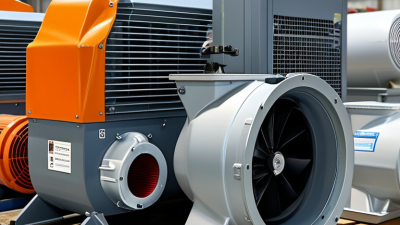
Choosing the right Centrifugal Fan is a practical engineering decision, not a catalog exercise. The fan must match the system’s real operating conditions. Airflow, static pressure, temperature, air density, noise, efficiency, and available power all matter. A small error can create large costs.
As AMCA fan specialist Mike Brackett puts it, “The fan must be selected for the system, not the catalog.” This principle deserves attention. A fan rated for 20,000 cubic meters per hour may fail when filters become dirty, ducts add resistance, or the installation changes. The published capacity is only one point on a performance curve.
Start with measured requirements. Record airflow and pressure at the duty point. Check whether the pressure is total or static. That difference can mislead even experienced buyers. Consider the air itself. Hot, humid, dusty, or corrosive air changes fan performance and material requirements. A backward-curved wheel may provide strong efficiency, while a forward-curved design may suit compact, lower-pressure applications.
Look beyond the first quotation. Compare sound levels, motor efficiency, speed control, maintenance access, vibration limits, and warranty support. Ask for certified test data when possible. Real installations rarely remain perfect. Filters clog. Belts stretch. Ductwork changes.
That is where selection becomes less certain. A spreadsheet cannot fully predict every field condition. Still, a documented system curve and cautious safety margin improve reliability. This guide explains the key checks, common mistakes, and practical questions that lead to a better Centrifugal Fan choice.

How to Choose the Right Centrifugal Fan?
Define Required Airflow (m³/h) and Static Pressure (Pa)
Start with the air volume, not the fan size. Airflow should reflect room use, heat loads, process emissions, and occupancy. ASHRAE Standard 62.1-2022 lists an office ventilation rate of 5 cfm per person plus 0.06 cfm per square foot. This equals approximately 8.5 m³/h per person and 1.1 m³/h per square metre. These figures describe outdoor air requirements, not always the total supply airflow. That distinction matters.
Static pressure represents system resistance. Measure or calculate losses through ducts, elbows, filters, dampers, coils, grilles, and terminals. Include the filter’s dirty condition, not only its clean reading. A fan rated at 10,000 m³/h may fail if the system requires more pressure than its performance curve allows. Use the actual duty point: airflow in m³/h and static pressure in Pa. ANSI/AMCA Standard 210 provides recognized methods for measuring fan airflow and pressure performance.
Field commissioning often reveals small errors. A forgotten flexible duct can add resistance. An underestimated filter loss can reduce airflow sharply. The first estimate is rarely perfect. That is normal, but it deserves review. Check the fan curve at the required duty point, then compare efficiency, noise, controllability, and motor margin. Do not select by maximum airflow alone. A larger impeller may create unnecessary energy use when the duct system is poorly balanced. Sources: ASHRAE Standard 62.1-2022, Table 6-1; ANSI/AMCA Standard 210.
Define Required Airflow (m³/h) and Static Pressure (Pa)
The chart compares typical ventilation requirements by application. Select a centrifugal fan that can deliver the required airflow while overcoming the system's total static pressure, including ductwork, filters, grilles, bends, and other components. The final selection should meet or exceed the design point without operating too close to the fan's maximum capacity.
Selecting a centrifugal fan starts with the required airflow and pressure, not the fan size. Fan laws provide a practical way to predict performance changes. At a fixed system design, airflow changes directly with speed. Pressure changes with the square of speed. Power changes with the cube of speed. For example, increasing speed by 10% may increase airflow by 10%, pressure by about 21%, and power by nearly 33%. That last figure is easy to underestimate.
Tips: Confirm the duty point using measured system resistance, air temperature, altitude, and density. Check the motor’s power margin. Avoid adding excessive safety capacity. It can create noise, wasted energy, and unstable control. Small errors matter.
Experienced technicians compare the fan curve with the system curve before approving a selection. The operating point should sit near the efficient region, while remaining clear of stall conditions. A fan that meets airflow at zero resistance may fail when filters become dirty or ducts become restrictive. Conversely, oversizing can force dampers to throttle constantly. I have seen calculations look correct on paper but perform poorly after installation because actual duct losses were overlooked. Recheck the assumptions. Measure vibration, current, and airflow during commissioning, then adjust speed carefully rather than guessing.
A centrifugal fan should be judged by total efficiency, not motor efficiency alone. Total efficiency measures useful air power against the fan’s input power. For many industrial applications, a practical target is 60–85%, depending on airflow, pressure, and operating conditions. AMCA Publication 208 explains that fan efficiency depends strongly on the duty point, not only the catalogue maximum. A fan rated at 85% may perform poorly after system resistance changes.
Check the fan curve carefully. Your required airflow should sit near the best-efficiency region, with pressure losses included. The U.S. Department of Energy’s Improving Fan System Performance sourcebook highlights duct restrictions, leakage, and throttling as common sources of wasted energy. A dirty filter can move the operating point quickly. That detail is easy to miss. Variable-speed control may reduce energy use, but only when the system actually needs changing airflow. Oversizing the fan often creates unnecessary damper losses.
Ask for tested total-efficiency data, operating noise, service clearances, and power consumption at your actual duty point. CIBSE Guide B recommends evaluating fans as part of the complete air-distribution system, rather than as isolated equipment. In practice, a 70% efficient fan with stable operation can outperform an 85% model selected from an unrealistic laboratory point. The numbers deserve checking. Even experienced engineers can over-trust a single efficiency figure.
How to Choose the Right Centrifugal Fan?
Select Materials for Temperature, Corrosion, and 80–120°C Air
Material selection begins with the actual air, not the fan catalogue. At 80–120°C, ordinary galvanized steel may lose durability, especially in humid or chemically active air. Carbon steel can work in dry, clean systems, but it needs a suitable coating and regular inspection. Stainless steel is often safer where moisture, chlorides, or acidic vapors are present. Grade 304 suits many general applications. Grade 316 is more appropriate for salty or chloride-rich environments.
Temperature affects more than the casing. The impeller, shaft, bearings, seals, and motor arrangement must match the operating condition. Hot air can weaken coatings, reduce lubricant life, and increase shaft expansion. A fan rated for short temperature peaks may fail during continuous operation. Check both normal and maximum temperatures. Do not rely on the average reading.
I have seen installations where the casing survived, but the bearings did not. That mistake was expensive. Use high-temperature bearings or move them away from the hot airstream when the design allows it. Consider an insulated housing, cooling wheel, or flexible coupling. Confirm the impeller’s balance after fabrication. Corrosion resistance alone is not enough. Material thickness, welding quality, airflow speed, and cleaning chemicals also influence service life. A practical selection should be checked against measured site conditions, not assumptions.
Choosing the right centrifugal fan requires more than checking airflow and motor power. Noise deserves equal attention, especially near offices, workshops, or occupied buildings. A practical target is below 85 dB(A), measured at a clearly defined distance and operating condition. The test should record speed, airflow, pressure, temperature, and microphone position.
Ask for complete performance data tested to AMCA 210 or ISO 5801. These standards help verify airflow and pressure under controlled laboratory conditions. They do not, by themselves, prove the fan’s acoustic performance. Noise results need separate test details, including background noise, duct arrangement, fan speed, and measurement location. Without these details, a single dB(A) number can mislead.
Look for test curves, not marketing claims. Compare the required duty point with the tested curve, then check whether the fan remains below 85 dB(A) at that point. A quiet result at low speed may disappear when the system resistance increases. I once trusted a noise figure without checking the test distance. The figure looked excellent, but it was not useful for the installation. That mistake changed my review process. Now I request raw readings, calibration information, and repeat-test conditions. Small gaps still matter. Ask questions before approval.
| Fan Reference | Airflow (m³/h) |
External Static Pressure (Pa) |
Rotational Speed (r/min) |
Sound Pressure at 1 m (dB(A)) |
Total Efficiency (%) |
Estimated Motor Rating (kW) |
Performance Test Basis | Noise Target < 85 dB(A) |
Selection Comment |
|---|---|---|---|---|---|---|---|---|---|
| Representative Engineering Duty Points | |||||||||
| CF-01 | 8,000 | 900 | 1,450 | 82.5 | 72 | 4.0 | AMCA 210 or ISO 5801 report required | Pass | Suitable for moderate airflow and pressure requirements where low noise is important. |
| CF-02 | 12,000 | 1,200 | 1,480 | 84.0 | 74 | 7.5 | AMCA 210 or ISO 5801 report required | Pass | Good balance between airflow, static pressure, efficiency, and acoustic performance. |
| CF-03 | 16,000 | 1,500 | 1,750 | 88.5 | 76 | 11.0 | AMCA 210 or ISO 5801 report required | Fail | High-speed operation may require a larger impeller, acoustic enclosure, or speed reduction. |
| CF-04 | 20,000 | 1,800 | 1,470 | 83.5 | 78 | 15.0 | AMCA 210 or ISO 5801 report required | Pass | Higher-capacity option with comparatively low rotational speed and improved efficiency. |
| CF-05 | 24,000 | 2,200 | 1,480 | 86.5 | 77 | 22.0 | AMCA 210 or ISO 5801 report required | Review | Verify the actual acoustic result under the installed operating point before approval. |
| Verification Criteria Before Purchase | |||||||||
| Airflow Capacity | Select a fan that meets the required airflow at the actual system resistance. | Allow for filter loading, duct losses, dampers, grilles, and safety margin. | Typical design margin: 5–10%, unless the system specification states otherwise. | Do not select by free-air airflow alone. | |||||
| Static Pressure | Compare the fan curve with the complete system curve. | Use the operating point rather than the fan's maximum pressure value. | Pressure data should identify whether it is total pressure or static pressure. | The reported test condition must match the intended duty point. | |||||
| Acoustic Verification | Target sound pressure below 85 dB(A) at the specified measurement location. | State distance, room condition, installation arrangement, and background noise. | Sound pressure is not directly interchangeable with sound power. | Check octave-band data when tonal noise or occupied-space comfort is important. | |||||
| Performance Test Standard | AMCA 210: laboratory methods for testing aerodynamic performance of fans. | ISO 5801: industrial fan performance testing using standardized airways. | The report should identify test setup, air density, speed, airflow, pressure, and efficiency. | Request the complete test curve, not only a single catalog point. | |||||
| Motor and Drive | Confirm motor rating from the calculated absorbed power at the selected duty point. | Check voltage, frequency, service factor, starting method, and variable-speed compatibility. | Direct drive generally reduces maintenance; belt drive may provide speed flexibility. | Include overload protection and verify operation across the control range. | |||||
| Important: The representative duty points above are engineering reference values for comparison. Final selection should be based on a signed performance test report or certified fan curve, with the noise measurement method and installation conditions clearly stated. Motor ratings are indicative selections based on airflow, pressure, and efficiency relationships and must be confirmed by the fan manufacturer or test laboratory. | |||||||||